
Products
 Back to products
Type E lattice girders
- E standard
- E with overlap


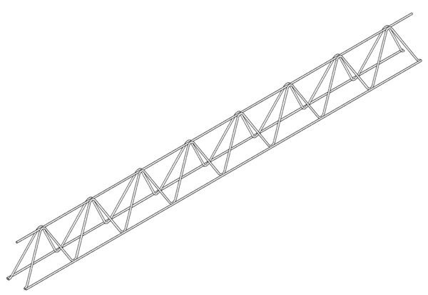
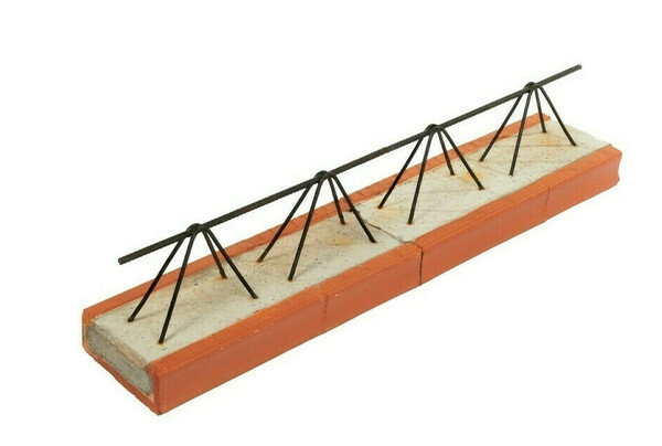
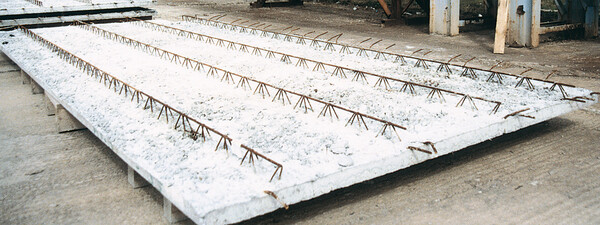
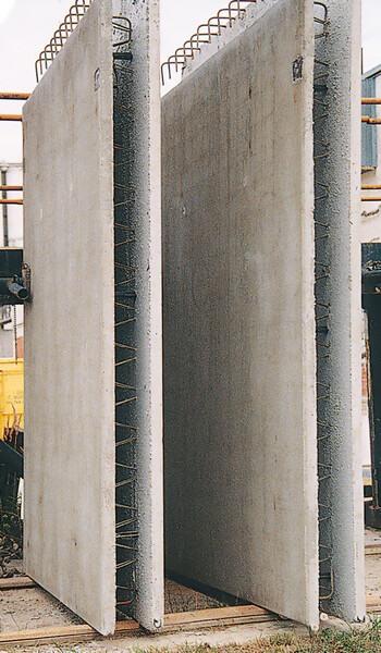

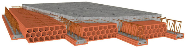
Spatial reinforcement type E - a comprehensive solution for effective and reliable reinforcement of reinforced concrete structures in construction. This type of spatial reinforcement is used in ceilings, ceiling beams and other ceiling structures, perimeter wall collars of family houses and industrial buildings, concrete lintels, filigree walls and slabs, composite walls (doubled).
The stability of this spatial reinforcement is ensured by two lower flanges and one upper flange connected by diagonals, and the use of higher wire diameters allows you to meet all requirements according to the project documentation.
With spatial reinforcement type E, you get a guarantee of precise compliance with the concrete cover and optimal steel distribution, which is key to the static strength and long service life of each structure. Our reinforcements are made of high-quality steel and meet even the strictest standards. They are therefore extremely reliable and durable. Another great advantage is that we can produce reinforcement in any length (in centimeters) from 1.75 m to 14 m and there will always be a cut at the end of the diagonal on the lower flange. The height of the product is from 70 mm to 400 mm. According to the customer's wishes, we can use both smooth and ribbed concrete steel for reinforcement.
The main advantages of using spatial reinforcement type E:
- quick and easy installation: minimizes the need for manual tying and shortens construction time
- guaranteed quality and accuracy ensuring consistent shape and dimensions
- high strength, which contributes to the overall stability and durability of reinforced concrete structures
- universal use: ideal for a wide range of construction projects, from family houses to commercial buildings
- can be produced in various lengths from 1.75 m to 14 m
- we offer reinforcement from smooth and ribbed concrete steel
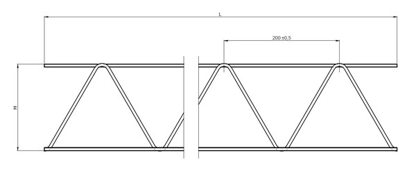
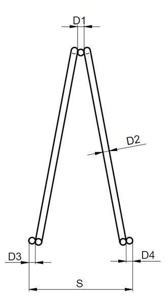
type E standard
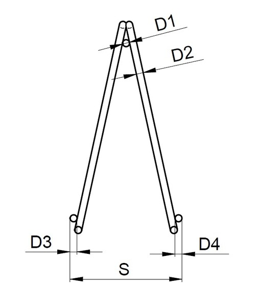
| Reinforcement parameters | Designation on the diagram | Reinforcement dimensions | Type of wire used |
|---|---|---|---|
| Reinforcement parameters: Upper flange diameter | Designation on the diagram: D1 | Reinforcement dimensions: 5 ÷ 14 [mm] | Type of wire used: B500A, B550A, B500A-G, B550A-G |
| Reinforcement parameters: Diagonal diameter | Designation on the diagram: D2 | Reinforcement dimensions: 4,6 ÷ 7 [mm] | Type of wire used: B500A-G, B550A-G |
| Reinforcement parameters: Bottom flange diameter | Designation on the diagram: D3 | Reinforcement dimensions: 5 ÷ 14 [mm] | Type of wire used: B500A, B550A |
| Reinforcement parameters: Bottom flange diameter | Designation on the diagram: D4 | Reinforcement dimensions: 5 ÷ 14 [mm] | Type of wire used: B500A, B550A |
| Reinforcement parameters: Beam height | Designation on the diagram: H | Reinforcement dimensions: 70 ÷ 400 ± 5 [mm] | |
| Reinforcement parameters: Beam width | Designation on the diagram: S | Reinforcement dimensions: 70 ÷ 110 ± 5 [mm] | |
| Reinforcement parameters: Beam length | Designation on the diagram: L | Reinforcement dimensions: 1 ÷ 14 [m] |
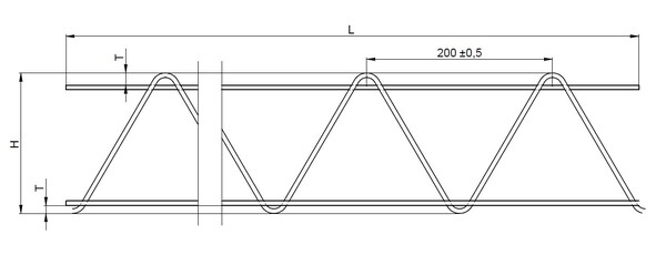
type E with overlap
| Reinforcement parameters | Designation on the diagram | Reinforcement dimensions | Type of wire used |
|---|---|---|---|
| Reinforcement parameters: Upper flange diameter | Designation on the diagram: D1 | Reinforcement dimensions: 5 ÷ 14 [mm] | Type of wire used: B500A, B550A, B500A-G, B550A-G |
| Reinforcement parameters: Diagonal diameter | Designation on the diagram: D2 | Reinforcement dimensions: 4,6 ÷ 7 [mm] | Type of wire used: B500A-G, B550A-G |
| Reinforcement parameters: Bottom flange diameter | Designation on the diagram: D3 | Reinforcement dimensions: 5 ÷ 14 [mm] | Type of wire used: B500A, B550A |
| Reinforcement parameters: Bottom flange diameter | Designation on the diagram: D4 | Reinforcement dimensions: 5 ÷ 14 [mm] | Type of wire used: B500A, B550A |
| Reinforcement parameters: Beam height | Designation on the diagram: H | Reinforcement dimensions: 70 ÷ 400 ± 5 [mm] | |
| Reinforcement parameters: Beam width | Designation on the diagram: S | Reinforcement dimensions: 70 ÷ 110 ± 5 [mm] | |
| Reinforcement parameters: Beam length | Designation on the diagram: L | Reinforcement dimensions: 1 ÷ 14 [m] | |
| Reinforcement parameters: Overlap of the lower and upper flanges | Designation on the diagram: T | Reinforcement dimensions: 10 ÷ 20 [mm] (flange overlap is optional according to customer requirements) |
Manufacture
About the company
We deliver to countries
Our products are exported with much success to Slovakia, Germany, Norway, Sweden, Poland and other countries
| 30 | Years of experience |
| 25 | Export to 25 countries |